Model Railway Forum banner

Insulfrog v Electrofrog???!!!! HELP ME!

39K views 32 replies 18 participants last post by  Sol  
#1 ·
Ok, so I have looked on the forum and read blogs etc but REALLY struggle with Electro vs Insulfrogs on points! All my layout is insulfrog and DCC - but I here everyone talking about using electrofrog? Why? What are the main reasons? Also, is it bad to be using insulfrogs?

Many thanks in advance for helping out a lost cause on this subject (me).
Image
 
#2 · (Edited by Moderator)
The problem with Peco Insulfrog points is that you can get momentary short circuits at the frog when metal wheels touch both rails which are of opposite polarity. The plastic insert is made as small as possible for cosmetic reasons. With DC you might see a small spark when this happens, but DCC systems are very sensitive to short circuits and can often react by shutting down.

Brian Lambert's website describes the problem well and what you can do about it.

Brian Lambert's Website
 
#4 ·
*** Its a good question to ask Ian:

Insulfrogs are one of several questions that come up regularly because retailers and trainset makers love to sell them as they are an "easy answer" to getting that first layout away from trainset oval to a more interesting layout that will encourage more loco purchases...

Conceptually they are fine, but in reality not so fine at all: As with anything that is an easy answer, there are compromises (potential stalling), direct issues (momentary shorts) and longer term pitfalls (non reversible lessened reliability over time as below) never seen by a new modeller in the early days of the hobby and these will create frustration and disappointment very quickly once they happen. These are all very real unfortunately.

The final thing that makes Insulfrogs a less wise choice for a permanent layout is their reliance on the tags on the blades for continuity of power through the blades. This always seems to work like a champion through track laying and testing, but inevitably becomes less reliable once you start committing to scenery, rail painting, ballasting etc....

That, plus the reasons from RFS and Erkut are why you will always see more experienced modellers advise against insulfrog.

There are several quite common subjects like this in our hobby - all can raise "but I use it/them and it works fine" from newer modellers, but time and experience inevitably show different results, which is why, having been bitten or seen / helped with these problems many times, experienced modellers will always strongly recommend a different approach, or perhaps specific methods, materials or equipment - or not as the case may be.

regards

Richard
 
#5 ·
I will be using Insulfrog points for the simple reason that Peco don't make Radius 1 Electrofrog. I know it's possible to convert them, but frankly that's beyond my current abilities.

I will, however, be mitigating the problems a bit. Firstly I will be insulating the exit rails from the frog to the remaining trackwork to prevent shorts. Secondly I'll add droppers to the exit rails and switch power, via the switches in the Cobalts, to get over the problems of solely using the blades as the power source.

Hopefully that will overcome the major downsides of Insulfrog. After that it will just be a case of making sure the loco pickups work OK to avoid stalling!

If anyone has better suggestions of course I'm always open to ideas.

Glen
 
#6 ·
My suggestion would be to redesign for the smallest electrofrog point you can find, something like the Peco 2' radius job. It isn't simply the conductivity over the crossing that is the problem with set track points, it is the geometry to acomodate the very tight radius, and a consequent lack of reliability in operation. If you have any ambition to reliably run trains more than four feet long, with no restrictions on the movements over the points, UK set track is a poor choice.
 
#7 ·
In many years of modelling, my previous DC layout was the first time I'd ever done 'proper ballasting' using the PVA/water method and boy did it cause me some problems. I was of course using insulfrogs and relying on point blade contact for electrical continuity - 'power routing' I believe it's called. The dilute PVA mix as it dried, covered the inside edges of the blades and also the tops of the little tags, only a slight film was present, but it really created a problem as my layout suddenly died (electrically) in various places. I know now that I should have masked the point blade before spraying but it is difficult to mask the tag which is an upward facing piece of metal sitting directly under and making contact with a rail. It also took a lot of getting rid of.

A couple of years ago I became a convert, went DCC and binned my old DC layout. With it went all of my insulfrogs and my new layout uses large radius Tillig electrofrogs throughout operated by a combination of Tortoise and Cobalt motors which switch the frog polarity, thus eliminating power routing. Provided you take the usual care when ballasting, particularly round the tie rods, my new points caused no greater problem than any ordinary piece of track - it certainly gets rid of the afore mentioned electrical problems when using insulfrogs. Running is also greatly enhanced and I get no stutters or shorts whatsoever over the points, no matter how slow the train or engine is going.

It's a 'no brainer' really, electrofrogs everytime. Just a pity it took my brain 40 odd years to appreciate it.

Mike
 
#8 ·
If I could get a small radius Electrofrog point I would. With a 4x2 N gauge layout however there is little choice available. Certainly with Peco the medium radius points are 18" which simply are not practical for what I want to do.

On the other hand most of my running will be tank engine + 1 coach which simplifies matters a lot!

Glen
 
#10 ·
In principle I think you are still correct to be honest. I'm aware that I'm making a compromise to fit the type of layout I want (i.e. an "operating" layout rather than a purely scenic one) into a small space. If I could stretch the baseboard a bit more I would, but it's just not possible at this stage.

Cheers

Glen
 
#11 ·
Use a peco PL-13 switch (or similar) to power the point rails and the frog according to the position of the switch.

1) Solder a wire to the frog, below the turnout.
2) Connect that wire to the "exit" terminal of the switch
3) Connect 2 wires to the entries of the switch, on for each rail at the entry of the turnout.
4) Use insulated joiners on the frog's exit rails, as customary.
5) You're done!
 
#12 ·
One thing a lot of people take too literally is Pecos advice to only feed the power to an Electrofrog point at its toe end. You can it fact feed the power to any point on any rail connected to the outside / toe rails. The typical example of this is the point situated at the platform end head shunt allowing the loco to run round. You need two long lengths of cable to take the power right down to its toe end whereas you can feed the power to the outer rails leading from the that point typically a good deal closer to the control panel
 
#13 ·
QUOTE (Glen P @ 19 Aug 2010, 09:21) <{POST_SNAPBACK}>In principle I think you are still correct to be honest. I'm aware that I'm making a compromise to fit the type of layout I want (i.e. an "operating" layout rather than a purely scenic one) into a small space. If I could stretch the baseboard a bit more I would, but it's just not possible at this stage.

Cheers

Glen
you can still have sharp curves on the loop ends and just use streamline live frog points for the sidings. you won't get as much in because the frog angle isn't as sharp. if you use code 55 for all of it you have a few more options to help save space with the slips and soon ( hopefully? ) the asymetric 3 way point.
 
#14 ·
I did try and fit the larger radius points in, but it still would mean severely reducing the operating aspects of the layout as there would be far fewer sidings, the passing loops would be too short, etc. One thing that doesn't help (if I've read things right) is that whilst Peco do an electrofrog point in OO with a 24" radius the smallest radius in N is 18". I might just have squeezed 12" radius in.

As I say I'm happy to accept the compromise for now. With a bit of luck the situaiton may change and I'll be able to devote significantly more room to the layout, at which point I'll definitely go larger radius.

Glen

(Apologies that a thread that started as Electrofrog v Insulfrog has turned into one about points radius)
 
#15 ·
OK, I have just bought a PECO streamline left Hand curve point (Electrofrog) - this is the first Electrofrog I have purchased! Can someone please explain why I have to use insulated joiners? I just don't get why? Surely I just need to wire droppers to it like the rest of the track?

Please help someone struggling on this matter!
 
#16 · (Edited by Moderator)
You need insulated joiners on the two frog rails as the frog polarity changes each time you change the points. If either of these rails has a fixed track feed downstream of the frog, then you will get a short circuit when you change the points.

Only if an exit rail leads into a siding which does not have its own track feed on that rail, can you dispense with the insulated rail joiner. However, for DCC it is recommended that all track is powered - even sidings - so that locos with sound and lights continue to function regardless of the setting of the points.
 
#19 ·
QUOTE (Glen P @ 20 Aug 2010, 08:58) <{POST_SNAPBACK}>I did try and fit the larger radius points in, but it still would mean severely reducing the operating aspects of the layout as there would be far fewer sidings, the passing loops would be too short, etc. One thing that doesn't help (if I've read things right) is that whilst Peco do an electrofrog point in OO with a 24" radius the smallest radius in N is 18". I might just have squeezed 12" radius in.

As I say I'm happy to accept the compromise for now. With a bit of luck the situaiton may change and I'll be able to devote significantly more room to the layout, at which point I'll definitely go larger radius.

Glen

(Apologies that a thread that started as Electrofrog v Insulfrog has turned into one about points radius)

in code 55 the smallest radius is listed as 12 inch, http://www.rmcq.mixedpk.com/worksheets/pec..._dimensions.pdf
also if you don't mind a bit of soldering onto copperclad sleepers?? i suggested in another thread that for code 80 trackage that the 009 point is bought ( also 12 inch radius ) and the sleepers replaced with N sized copperclad, and if in hidden storage loops just leave as is.
 
#22 ·
This is also a topic that interests me - I'm also new to Electrofrog and want the benefits - especially of short wheelbase locos not stalling on the frog (as they do on Insulfrog).

although this thread has been dormant for a while - I hope someone can still help...

The feedback given (especially by Taigo on 19/Aug) is that Peco recommend a PL-13 switch which has to be fitted under a point motor - meaning the entire point must be motorised (kinda obvious statement I know...
Image
)

My question is simply - does it have to be motorised? As PL13 usage seems synonymous with a point-motor, is there an equivalent manual solution (which I guess would require some adaptation of the wiring mandated by Peco on their turnout leaflet and perhaps a different switch model. Or would I then have to physically move the points AND flick the switch to reverse frog-polarity, at the same time.?

Or is there any completely alternate way of wiring Electroforgs for DCC. I've looked at Brian Lamberts site - although I've relied on it in the past for other things - on this topic I don't really get it.
 
#23 ·
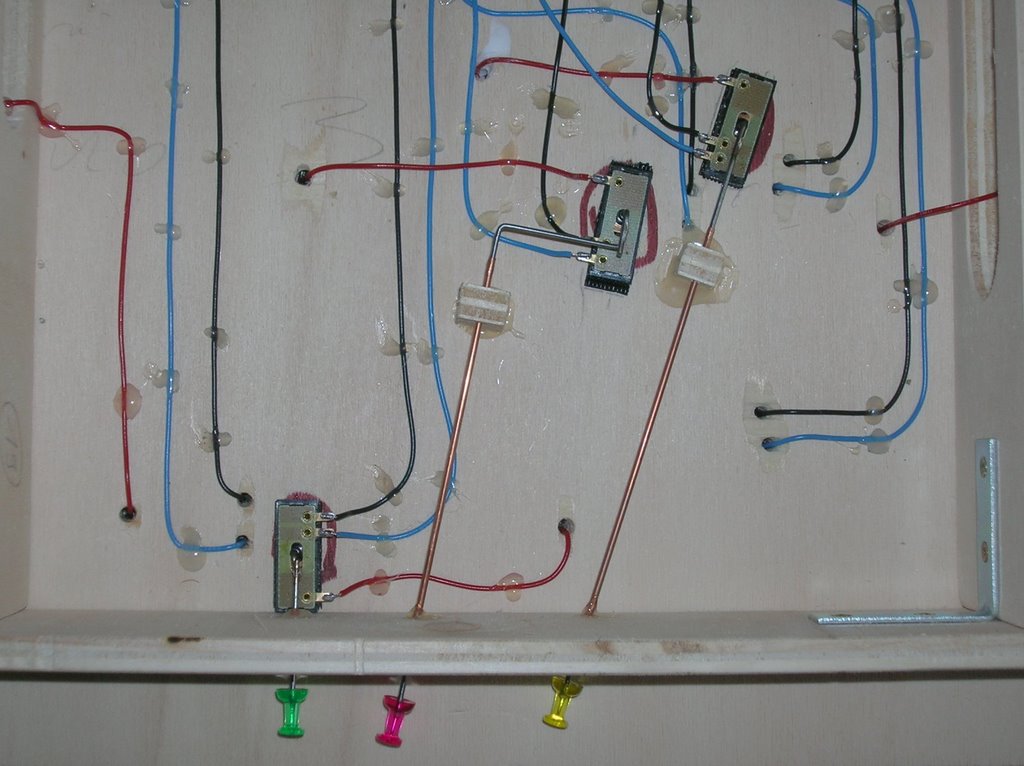
Thing is, the PL-13 is especially designed to fit underneath the PL-10 engine. The beam from the motor fits through a hole on the PL-13 and synchronizes it's movement with the point current position.

It doesn't have to be motorised. (Actually, I simply hate those peco vertical motors). Neither must you change the turnout wiring. Any setup that you might come up with will do the trick. As long as that wire that is connected to the underside of the turnout is connected to the proper rail for every position of the turnout.

Here's an example of someone with your exact problem:

Check this guy's blog:
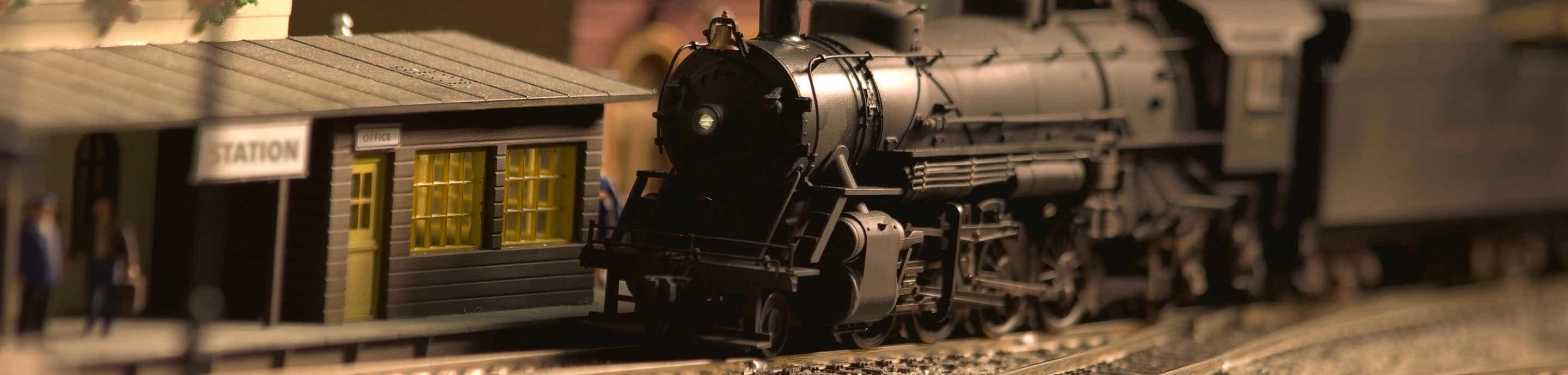
Stazione di Cretaz

In this picture:

Image

Image


The guy used a small beam which he uses to manually change the turnout. That beam changes the PL-13 and the turnout at the same time.

Cheers

QUOTE (sennapod @ 13 Oct 2010, 15:44) <{POST_SNAPBACK}>This is also a topic that interests me - I'm also new to Electrofrog and want the benefits - especially of short wheelbase locos not stalling on the frog (as they do on Insulfrog).

although this thread has been dormant for a while - I hope someone can still help...

The feedback given (especially by Taigo on 19/Aug) is that Peco recommend a PL-13 switch which has to be fitted under a point motor - meaning the entire point must be motorised (kinda obvious statement I know...
Image
)

My question is simply - does it have to be motorised? As PL13 usage seems synonymous with a point-motor, is there an equivalent manual solution (which I guess would require some adaptation of the wiring mandated by Peco on their turnout leaflet and perhaps a different switch model. Or would I then have to physically move the points AND flick the switch to reverse frog-polarity, at the same time.?

Or is there any completely alternate way of wiring Electroforgs for DCC. I've looked at Brian Lamberts site - although I've relied on it in the past for other things - on this topic I don't really get it.
 
#24 ·
#25 · (Edited by Moderator)
Hi sennapod,

I think Grahame's article just about covers the re-configuration and wiring aspect of the turnout but I would add that there is an alternative motor to the ubiquitous Peco one.

I use Seep PM1 motors which have 6 termiinals on them so that the polarity of the frog is automatically changed when the point is thrown. This avoids the need for a separate switch to control frog polarity.
 
#26 ·
Two remarks:

1) The pictures i posted earlier are not appearing, but visiting the blog I will reveal all the details.

2) I'm using code 80 PECO turnouts. As I said before, I don't see the necessity of mutilating the turnouts cutting bits of it. Perhaps code 100 ones are different.

I'm still assuming that, in code 80, the closure and the respective point rail are electrically connected, so the standard modification (as popularized in wiring for DCC) is, in my opinion, unnecessary.

Additionally, I strongly recommend against any hardcore turnout modifications. Last time I attached a PL-10 motor to a Peco turnout the tie bar snapped out of it's place. They are quite fragile.